ObiWanStenobit
Just before the Christmas holidays, I was contacted by Emily from PCBWay.
Since she liked the Neopad
and the LATE-9 projects,
she wanted to sponsor me by producing a batch of PCBs for these macropads for free!
Leaving aside the excitement of being contacted by a major manufacturer like PCBWay,
I chose to take this opportunity and, rather than revisiting old projects, design something entirely new for this occasion.
Emily agreed and gave me complete creative freedom.
I started thinking about what kind of project I wanted to make.
For quite some time, I had wanted to design a split keyboard.
But I didn’t want to create just another iteration of the Corne
or the Ferris.
We’ve all seen plenty of them, and we already know they are top quality.
I wanted to create something unique.
Another thing on my to-do list was learning stenography
(a chord-based typing system that allows insanely fast writing).
And then I thought: what if I combine these two ideas?
As major goals, I set cost reduction and portability.
Consequently, the PCBs needed to be small (maximum 100x100mm), both to qualify for lower production costs
and to achieve a compact final footprint. Components also had to be minimal and commonly available.
As a secondary objective, easy solderability and assembly were important as well.
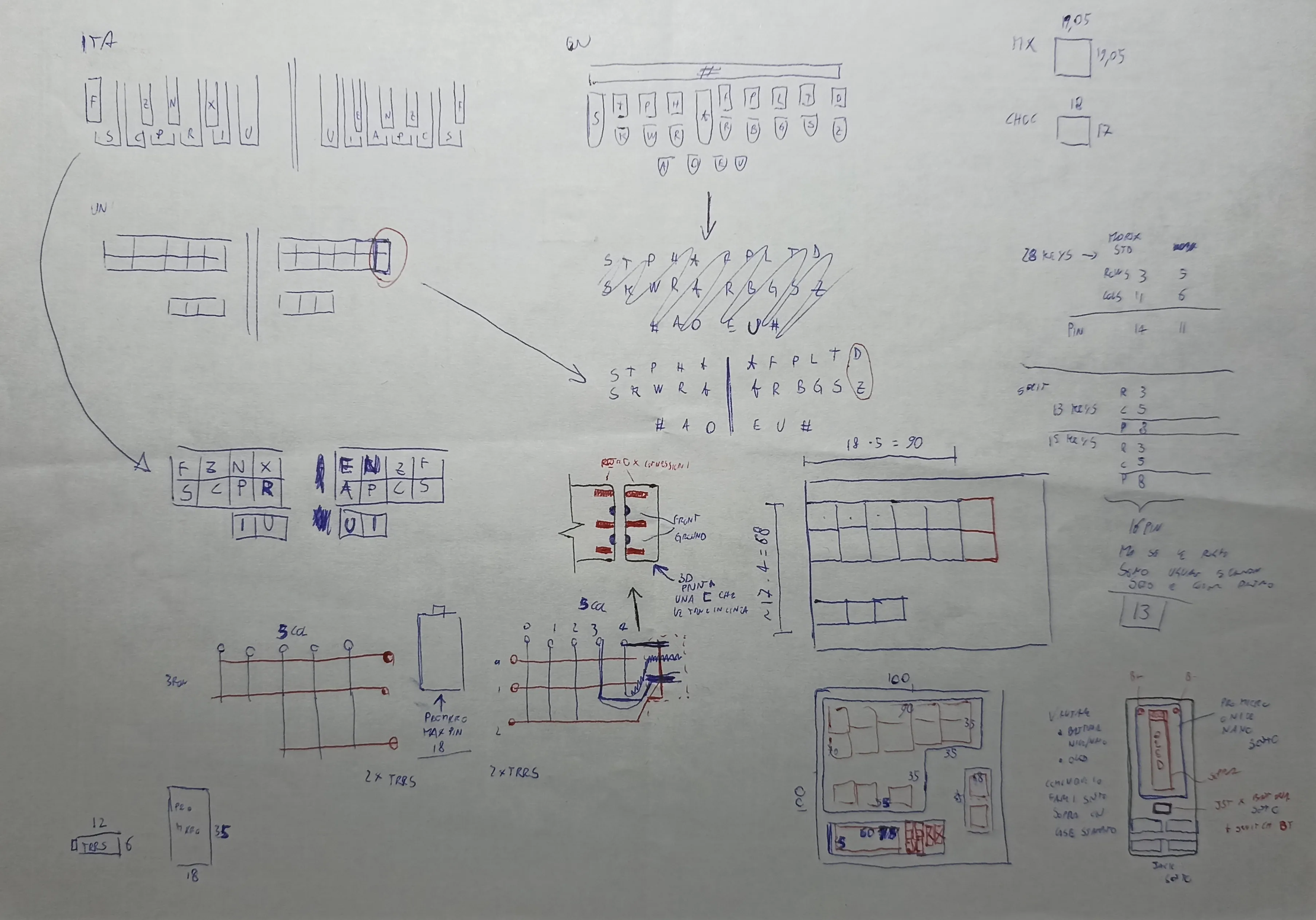
Starting from the layout, I soon noticed that I needed more keys than I could fit within a length of 100mm.
Take, for example, the most famous steno keyboard, The Uni:
you can see that each row has 5+6 keys.
The choice of an asymmetrical layout was explained by
Peter Park,
and I liked the idea of following it.
A split with 6 keys on a single row was not possible within a 100mm width. Quick maths.
MX switches have a footprint of 19x19mm, so 19x6 = 114mm. I was already over the limit.
I turned my attention to Kailh Choc switches,
since they are low profile and narrower, perfect for a steno board.
Their footprint is 18x17mm, for a total width of 18x6 = 108mm. Still too much.
So I had to get creative.
Since the left side would have only 5 columns, I could create a base PCB with just 5 keys per row,
and move the 2 extra keys onto a separate expansion PCB attached on the right.
Instead of creating a break-off column like the
Kyria,
I would create a column meant to be attached.
The complete opposite. A weird idea.
I liked it!
Obviously, this needed to be double-sided to avoid having to place two separate orders.
Since the minimum quantity is usually 5 PCBs, I could make 2 full keyboards from a single order and still have a spare PCB as a keepsake.
This would also be perfect for through-hole construction, because the holes are already available on both sides.
Using two controllers like in a standard split would have increased the cost.
So I asked myself: what if I use a single controller to manage both halves, as if they were one keyboard?
After all, the matrix would look like this:
- right side: 15 keys → 5 cols and 3 rows → 8 signals
- left side: 13 keys → 5 cols and 3 rows → 8 signals
That’s 16 pins total, and a Pro Micro (or another footprint compatible controller) provides 18. Nice.
I assumed the controller should not sit on the main halves like in a typical split keyboard,
because on one side it would waste valuable space.
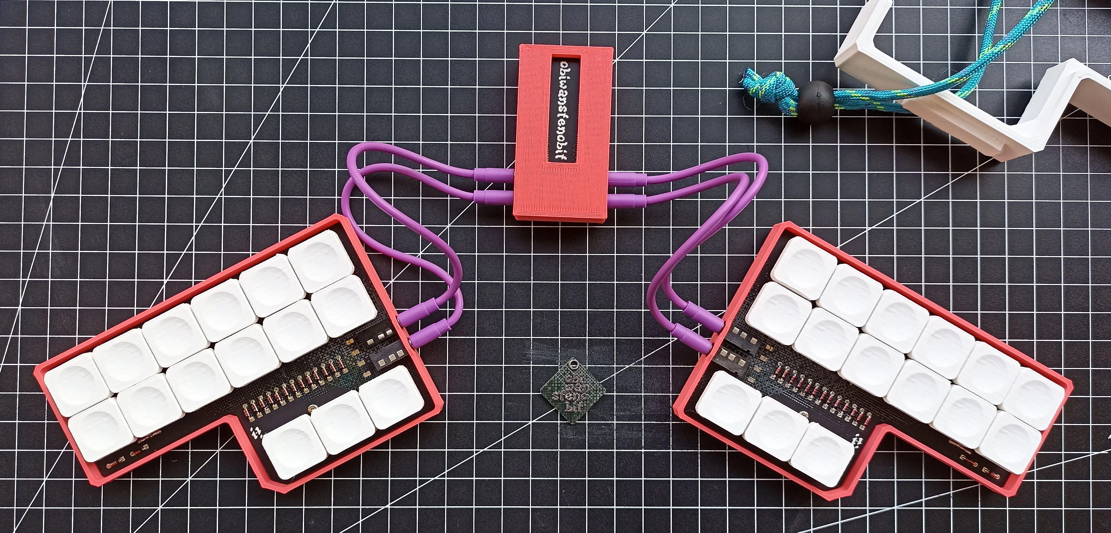
Instead, I would create a third little board, a “bay”, that sits in the middle between the two halves,
leaving freedom for positioning and tilt of the halves for better ergonomics.
To bring the key signals to the controller, I could use an 8-wire cable.
The first solution that came to mind was an Ethernet cable.
But after thinking about it for a while, I convinced myself that two 3.5mm TRRS jacks were a better choice:
they are easily available, more flexible, and have smaller sockets.
They also give users much more freedom for customization, since cables can be made without special tools.
Done. Each side would have two TRRS sockets to connect to the central bay that accommodates the controller.
Doing some more maths (I like maths), I realized I could share rows to save controller pins.
Now I would only need 13 pins, with a matrix of 10 total columns (5 per side) and 3 rows.
I started sketching the first PCB ideas:
- a main body with 5 columns and 3 rows, where the third row has only 3 keys and is spaced apart to leave room for the thumbs
- an expansion PCB with only 2 keys, to be soldered onto the right side of the right main PCB
- a PCB for the MCU and jack sockets
To join the expansion PCB to the main one, I decided to solder edge pads and reinforce them with a header pin. I had already seen this construction on the Adafruit NeoTrellis when boards are stacked together.
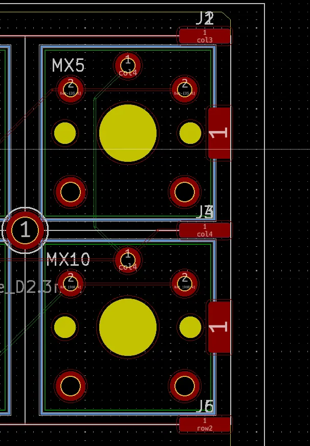
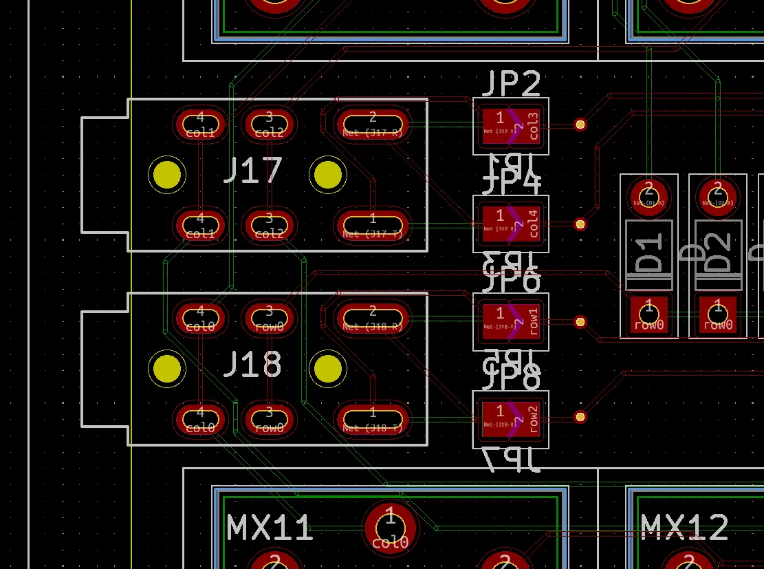
All the footprints on the main body needed to be mirrored to allow assembly on both sides.
Not a hard task, since the only components were diodes, switches, and jack sockets.
The diodes were through-hole, so they required no customization. The keyswitches simply needed mirroring along the vertical axis.
Sockets, on the other hand, required a certain level of abstraction.
When mirrored longitudinally, pins 3 and 4 end up overlapping. I needed a way to invert the pins depending on which side the user soldered.
I came up with the idea of using jumper pads on both sides.
By soldering the pads on one side, the pins would be routed differently.
I chose to always solder the four jumpers on the backside of the PCB, to keep the front clean.
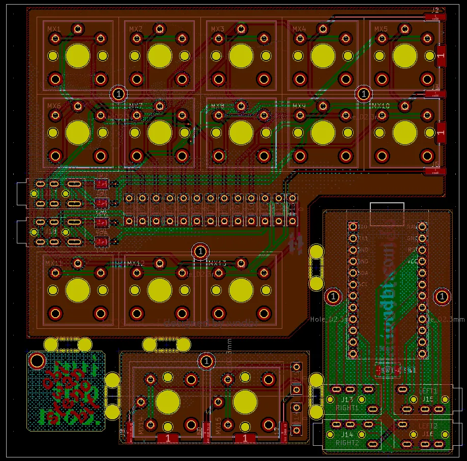
The dimensions were now defined.
I positioned the three PCBs within the 100x100mm square.
A simple puzzle, since all three were compact, and I confirmed early on that it was feasible with some margin.
I noticed unused space in one corner. Maybe I could add something to make use of it.
Why not a keychain?
I had already made PCB keychains before,
and many of my friends liked them. This could be a nice extra.
One part of the project I never spent much time on was the graphics.
I usually don’t care much.
I just want to place the order quickly and get the boards in my hands.
But this time was different.
I wanted to make it pretty and personal so I chose to include some elements I love:
- classic Greek/Italian art
- brutalist architecture (concrete!)
- pixel nerd aesthetics
After some iterations, I created what you can see below.
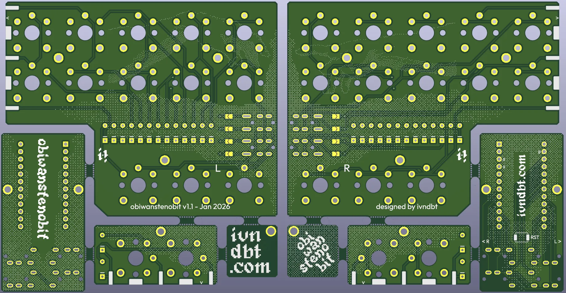
All the elements I wished for were there:
- the iconic hands from The Creation of Adam by Michelangelo, one on the front, one on the back, recreating the frame when placed side by side
- the silhouette of the Quadrilatero in Trieste, cropped and mirrored to create the gradients
- dithering effects to keep everything consistent

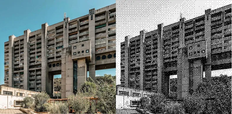
The dither effect was made on Ditherlicious.com after some manipulation in GIMP and some tips by Karl B.
At last, I found the name: ObiWanStenobit, or OWS for friends.
I added the logo using the Kiwi Soda font
on the front side of the controller PCB.
I decided to mount the controller on the bottom side for a minimal final look.
Some extra text and symbols were added to help with assembly.

On Thursday, everything was ready for the order. And here comes the sponsor of this post:
PCBWay.
As mentioned at the beginning, they handled production and shipping of the prototype. The service was excellent and fast.
I uploaded the Gerbers, selected the specifications I wanted, chose PCB and silkscreen colors, and confirmed the order.
After just a couple of hours, a technician reached out to clarify and fix a few selections.
For example, I chose the option “exposed pads” because I thought the pads used to join the main and expansion boards counted as such.
They didn’t. The technician caught the mistake and asked for confirmation before fixing it. Awesome.
The day after, I talked to Emily and completed the order. It was Friday.
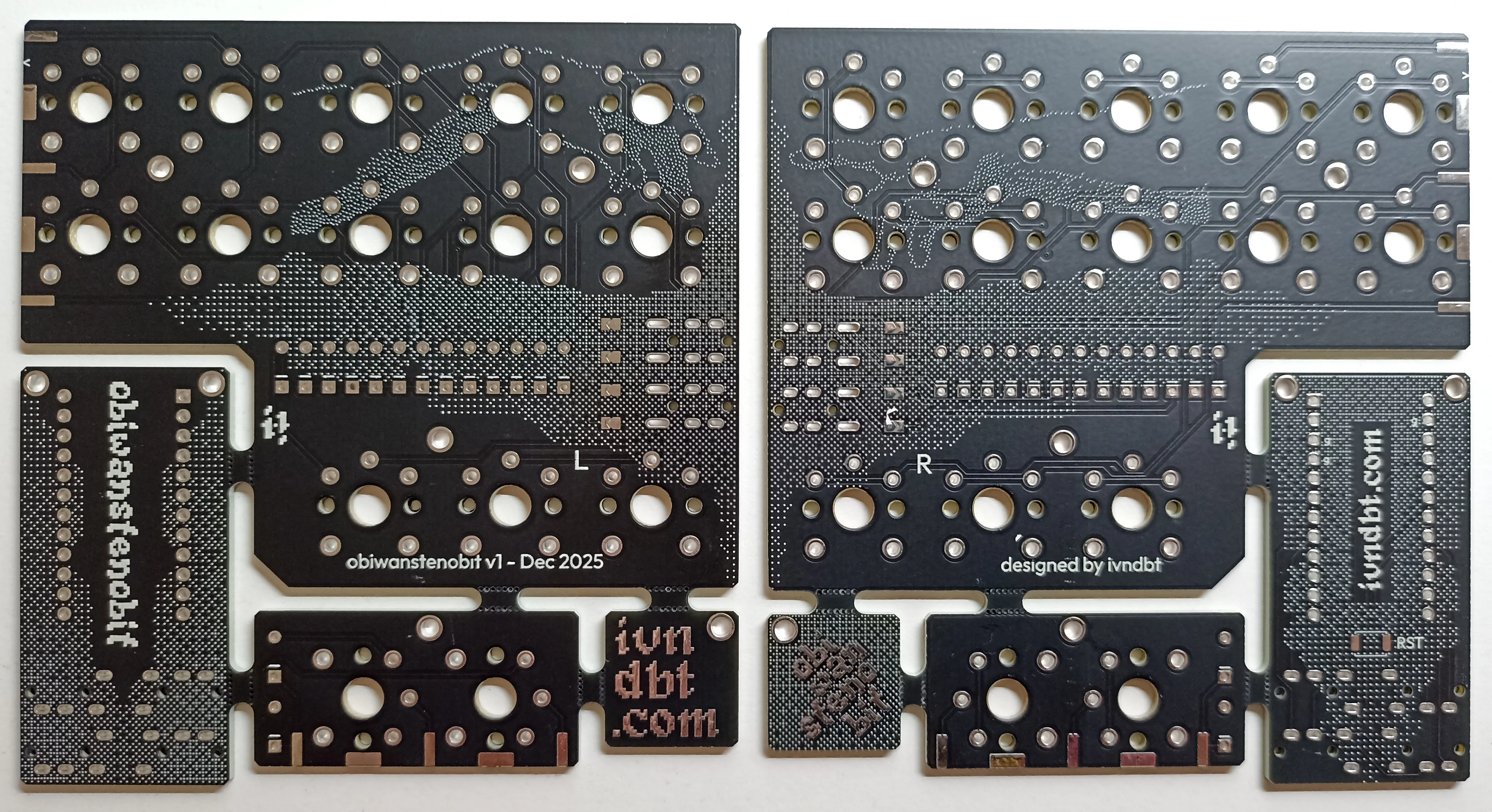
On Monday, I received the email that the PCBs were ready to ship. On Wednesday, they left. On Friday, they arrived. Insane!
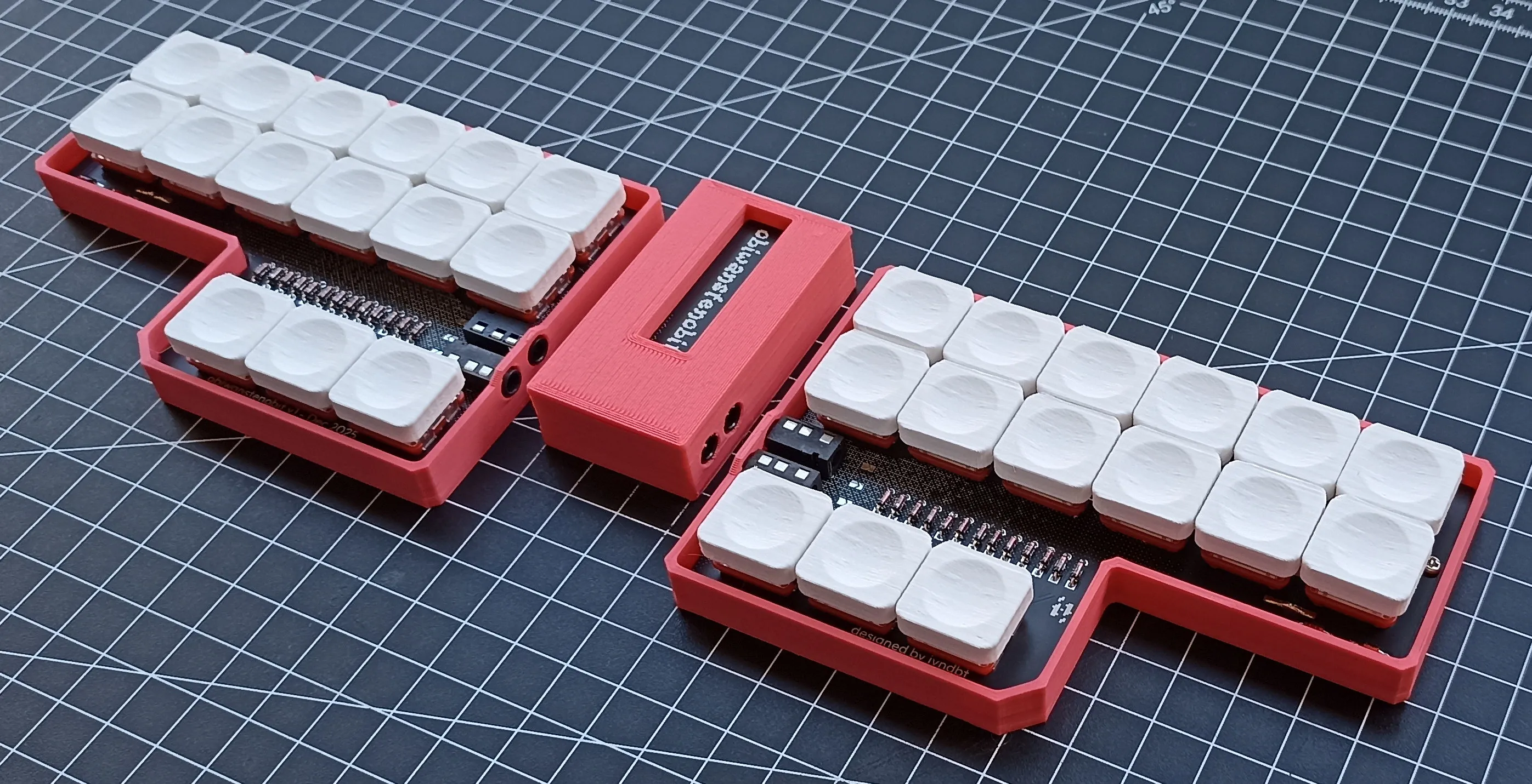
For production quality, I think the best is to let you look at it.
The crispness of the silkscreen is excellent, and I’m very happy with the final result. It's even better than the KiCad render!
The assembly went well too. In a couple of hours, I soldered everything.
Most of that time was spent placing Mill-Max pins into the sockets, lol.
I won’t describe the full build here because I made a
step-by-step guide in the
official repository.
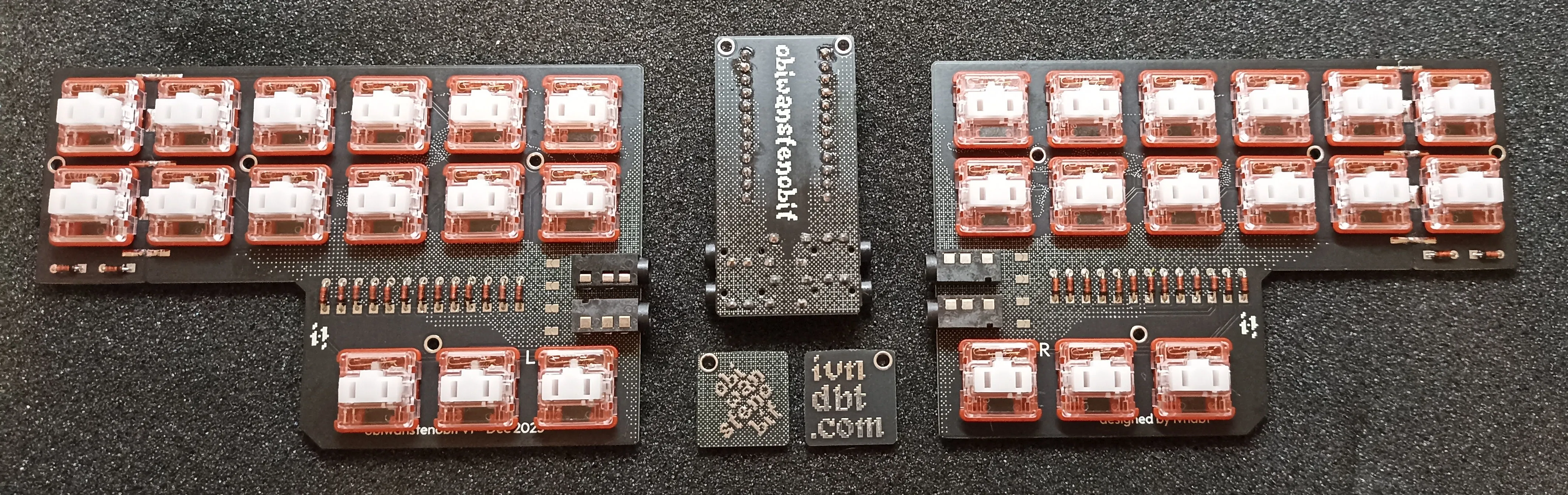
For the controller, I used a nice!nano v2 that I had lying around. Because of that, I built the firmware in ZMK.
I had only learned ZMK recently for a collaboration project coming out this year, and once you get used to the workflow,
it’s very straightforward and easy to configure.
The simplicity of the keyboard made the work smooth.
Plover setup was a bit more complex. Because my system input is Italian,
I had to remap a few keybindings and use the “keyboard” protocol instead of a proper steno one.
This is one of the current limitations of ZMK compared to QMK.
The idea behind using the nice!nano (and writing a ZMK firmware for it) was to enable Bluetooth support just by adding a 301230 battery.
For the RP2040, I made a QMK firmware using the GeminiPR protocol.
Here I had more fun and added layers with navigation bindings and even a QWERTY layer.
It’s very useful to toggle between steno and QWERTY, but unfortunately,
this is only possible if the firmware supports steno protocols, otherwise it ends up overwriting the standard input.
With ZMK, I have to disable Plover to type in QWERTY, or use another keyboard connected to the PC.
So depending on the controller, you get different trade-offs.
As you may have noticed, for each firmware I wrote layouts keeping all 30 keys (including the 2 extra keys even on the left half).
During development, I realized those extra keys would be useful for layer switching, so I made them default.
Because of the stenographic nature of the keyboard, many key combos are already occupied for writing,
leaving little room for layer switching.
Still, nothing prevents building a more compact version with only 28 keys without changing anything in the firmware.
It's just a matter of preference.
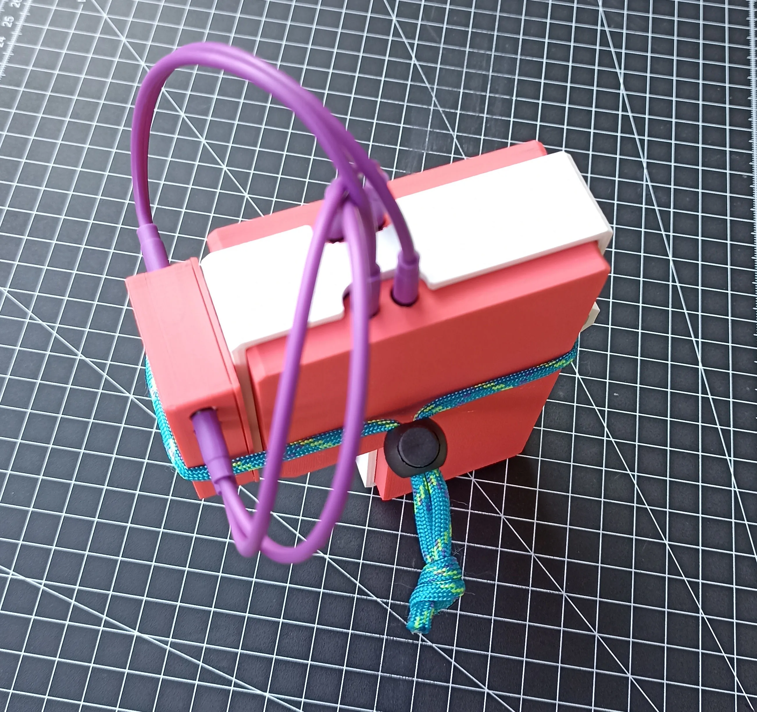
At this point, I focused on portability.
I wanted a travel-friendly keyboard that could be tossed in a backpack without fear of damaging the keys.
I thought of a shell system to close and protect it. I designed and printed everything, including the keycaps.
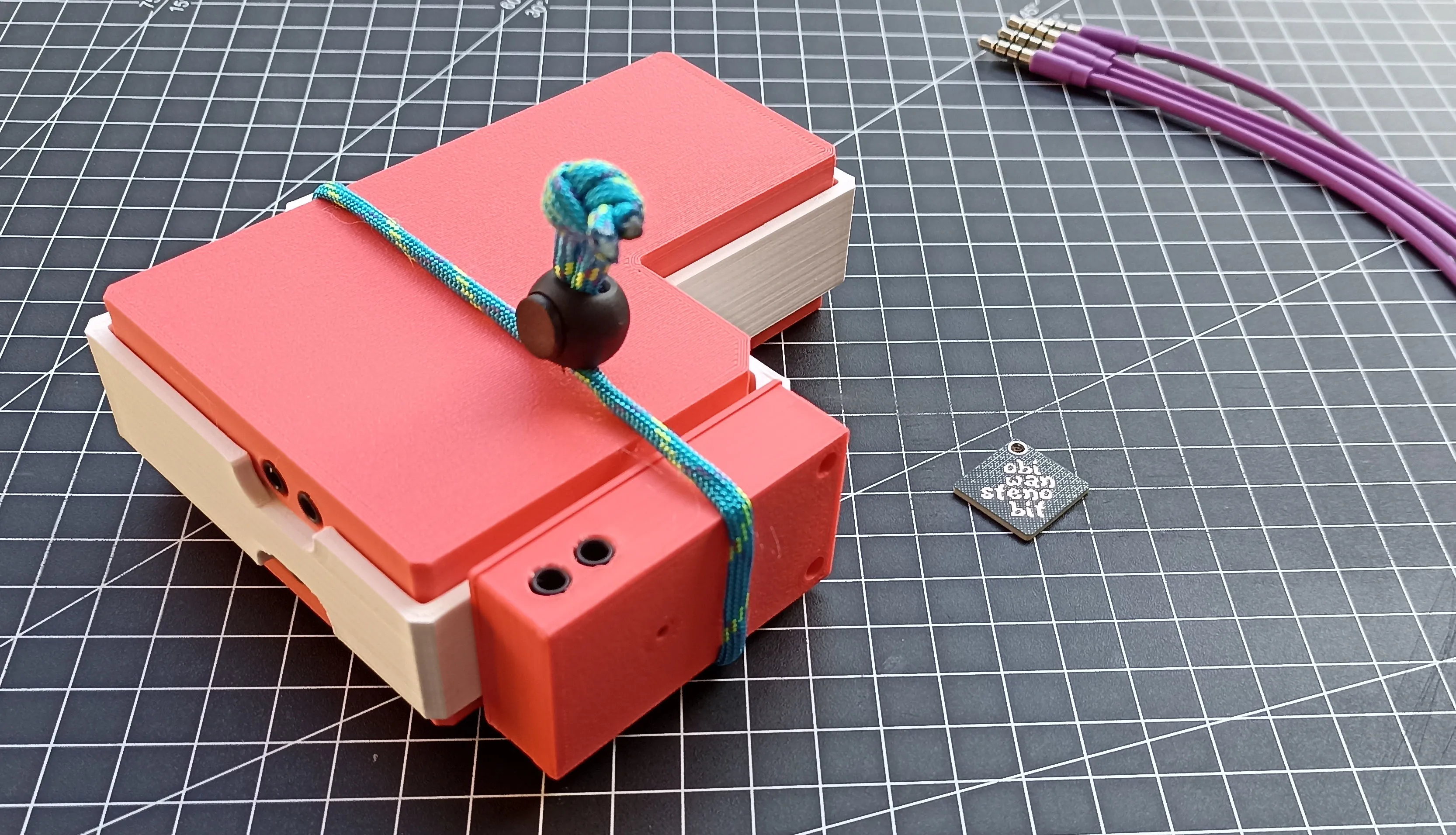
The white piece is the holder that keeps everything secured with a strip of paracord. The keyboard can be stored even with cables still connected, allowing for an even faster deployment.
The open-source version (1.1) differs from my prototype with a couple of minor bug fixes:
- added the missing silkscreen on the expansion board
- widened the bay by 3mm to better accommodate the case screws
I’m very happy with how this project turned out. In just one month, I designed, prototyped, and coded it.
I can’t wait to see it in other people’s hands and help spread stenography!
If you’re interested in building one, you can find all the sources
here.
If you have any questions, feel free to contact me.
And if you build one, send me a picture, and you’ll make my day!
February 2026 update: VIA, Vial and Javelin alternative firmwares are now avaiable!
Plus, the keyboard was featured on kbd.news.